Discussion Forum - Northstar Chevelle Club
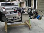
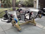
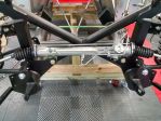
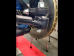
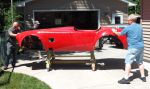
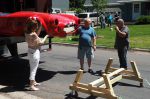
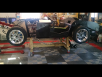
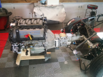
Members Login
Username 
 
Password 
    Remember Me  
Post Info TOPIC: Factory Five Mk4 Roadster Build - 40 Watt Garage


2K+ Club

Status: Offline
Posts: 2791
Date:
Factory Five Mk4 Roadster Build - 40 Watt Garage
Permalink  


Been doing a lot of work on the floorboards and rear cockpit/trunk panels. I made a few panels that aren't included in the kit, but will make carpeting the trunk much easier. They cover the frame tubes on the upper trunk area (above the coil-overs).

Used the air nibbler to rough-out the panels. Upside = it zips through sheetstock like butter. Downside = there are about 387,549,326 little half-moon razor blades all over (ejected cuttings). Had an enforced shop cleanup & vacuum session... so kit #9365 got some fresh air & sunshine for a few hours.


Attachments
__________________


John D. - St. Louis Park, MN.

1965 El Camino - LT-1, 4L60e, 4wh discs, SC&C susp.
2013 F-150 Platinum - Twin Turbo 3.5

2018 Factory Five MkIV Roadster build thread


President

Status: Offline
Posts: 7274
Date:
Permalink  
 

I have one of those nibblers and used it ONCE for the very same reason...way too many sharp cuttings flying around.
Car is coming right along...thumbsup


__________________

Mitch D.   River Falls, WI

Lifetime member of the "Cars apart Club"

Some Assembly Required

1966 Chevelle SS 396 M20

1970 Chevelle SS 396 M20

1967 Camaro SS 350 rs


2K+ Club

Status: Offline
Posts: 2791
Date:
Permalink  
 

I have one of those nibblers and used it ONCE for the very same reason...way too many sharp cuttings flying around.

Yeah, I really do know better, and when I use the tool I usually put the sheetstock over the trashcan - then the little buggers just fly into the can, problem solved.
I had to buy a 36x36 sheet to get the long-dimension length I needed, and with all the crap in the shop I had to cut where there was space.

(Anyone looking for a kick-azz sewing/quilting machine? I gotta get this thing outta here.)


__________________


John D. - St. Louis Park, MN.

1965 El Camino - LT-1, 4L60e, 4wh discs, SC&C susp.
2013 F-150 Platinum - Twin Turbo 3.5

2018 Factory Five MkIV Roadster build thread


2K+ Club

Status: Offline
Posts: 2791
Date:
Permalink  
 

A few updates coming ...
I really didn't realize how many of you were really following this build, and had interest in it. Like I've said, this is the fulfillment of a 35 year ambition - I'll never afford a real one, so I'm building a replica. On to the progress report.

The 2nd to last of my backorder items arrived (Tie Rod Ends), so I could finally mount the power rack & pinion setup. Again... I LOVE NEW PARTS!! The unit is a brand-new replacement for a 2015+ Mustang, and the only thing needed is to swap out the supplied bushings (for Mustang) with the provided (FFR) bushings.

FFR's jigs and welders must be totally pro's. The rack dropped in without the slightest fight. A little nudging with some big drift punches through the holes and the bolts pushed in by hand. The steering shaft is stainless "welding porn", and I'm really tempted to sit in it and make engine noises now.

(Can't do it. My steering wheel hub is in CA, being modified for turn signals.)


-- Edited by John D on Monday 27th of August 2018 08:12:15 PM

Attachments
__________________


John D. - St. Louis Park, MN.

1965 El Camino - LT-1, 4L60e, 4wh discs, SC&C susp.
2013 F-150 Platinum - Twin Turbo 3.5

2018 Factory Five MkIV Roadster build thread


President

Status: Offline
Posts: 378
Date:
Permalink  
 

When you are sitting in it, play this video.

www.youtube.com/watch

__________________

Hankster

Columbus, MN

'71 Chevelle SS frame-off, restro-mod, 402/375hp, Tremec TKO 600 5-speed, 3:90 12-bolt posi

'60 VW Beetle currently in the CAC


2K+ Club

Status: Offline
Posts: 2791
Date:
Permalink  
 

The next few updates deal with the firewall and the impact of options on it.

The FFR assembly manual has a few discrepancies. "Out of the Box" it is written & printed for the basic kit with no options - and you could build the car page by page and not have a problem...
- Enter Options... such as windshield wipers, heater/defroster, Coyote engine.

Each of these options have an impact on the firewall. They're either mounted to it, and/or wiring for them penetrate through it.

Permanently mounting/riveting the firewall to the frame assembly is one of the very early steps in the assembly manual... which is fine - If you're building without the above options! Once this panel is mounted to the frame, it would be VERY difficult to jig-up, mark, drill and mount the "options".
I am going to send out a letter to FFR, and ask them to put an addendum in the manual. Nothing major, but just a *** "Hey, if you're installing xxxyyyzzz... STOP, refer to the instructions for this option BEFORE mounting the firewall"***

Wipers:
Mounting of the wiper motor is dictated by the space left over after punching the firewall for the heater...

Heater:
FFR/Vintage Air supplies a very nice template for cutting the firewall... except it isn't quite perfect. The holes for the inlet/outlet aren't quite in the right spots. The pic shows just how much "off" the inlet/outlet holes are. Measure twice... cut Once.
Heater01.jpg

Wipers:

The wiper motor gets whatever space is left over when the heater box is mounted. The basic instructions are to mount the motor with the drive cable pointed in a smooth arc to where the wiper arm boxes will be. This tucks the wiper motor in the left-most corner of the firewall. I wasn't satisfied with mounting the motor on the .040" aluminum panel. A little flimsy for my tastes. I made up a mounting bracket for the motor that ties it to the major crossmember of the dash.

Wiper_01.jpg

Wiper_02.jpg

Wiper_03.jpg

Wiper_04.jpg

Wiper_05.jpg

Wiper_06.jpg

Wiper_07.jpg

Wiper_08.jpg

Wiper_09.jpg

Wiper_10.jpg

Wiper_11.jpg

Wiper_12.jpg


Attachments
__________________


John D. - St. Louis Park, MN.

1965 El Camino - LT-1, 4L60e, 4wh discs, SC&C susp.
2013 F-150 Platinum - Twin Turbo 3.5

2018 Factory Five MkIV Roadster build thread


Vice President

Status: Online
Posts: 477
Date:
Permalink  
 

John D wrote:

A few updates coming ...
I really didn't realize how many of you were really following this build, and had interest in it.


-- Edited by John D on Monday 27th of August 2018 08:12:15 PM


 I think there are a lot of us that are very interested, I like seeing the progress, the improvements that you have made, the craftsmanship, and, the humor is always good to.


__________________

Bob W.

Lino Lakes


President

Status: Offline
Posts: 7274
Date:
Permalink  
 

Mr. CDO at work again, making a product better. I'm betting you are looking at that lower rack line thinking "that looks vulnerable to road debris hanging that low. I'd better make a shield that attaches with the rack bolts to protect it"...


__________________

Mitch D.   River Falls, WI

Lifetime member of the "Cars apart Club"

Some Assembly Required

1966 Chevelle SS 396 M20

1970 Chevelle SS 396 M20

1967 Camaro SS 350 rs


2K+ Club

Status: Offline
Posts: 2791
Date:
Permalink  
 

Firewall - Electrics

The wiring for the main harness & engine sending units, then the wipers, heater, & front body lighting all require a path through the firewall. Add in the necessary feeds from the Ford Performance ECU for the Coyote engine and there's a lot of wire that needs to get from the engine bay to the cockpit!!

FFR does provide a detailed description of where to punch the holes for the wiring grommets, but (again) has forgotten about "options". If you punch the holes for the Coyote ECU harness, and mount the underhood fusebox as described - it FOULS the connection to the heater core for the coolant hoses.

(again... measure twice, cut once.)

I had to sneak the Coyote ECU harness hole a bit to the driver's side, and mount the underhood fusebox a bit forward of the prescribed location so there's free-air to the heater core fittings. (If someone was "cookbooking" this thing together pagebypage they'd be in a problem).

Firewall_01.jpg

Firewall_02.jpg


** Tip for drilling sheetstock with a holesaw**

Securely clamp the workpiece to the bench with a "sacrificial" block of wood under. Pre-drill through the stock with the diameter of the pilot-bit of the holesaw into the block. Chuck up the holesaw, and touch-off on the workpiece BACKWARDS a few dozen turns! This will start the "groove" the holesaw will cut on. Stop the drill, reverse to the "correct/RH" rotation, and cut the hole. This will help minimize "wander" of the holesaw and give you a clean hole.

Firewall_03.jpg

Firewall_04.jpg

Firewall_05.jpg

Firewall_06.jpg

ECU35.jpg

Firewall_07.jpg

Firewall_08.jpg


Attachments
__________________


John D. - St. Louis Park, MN.

1965 El Camino - LT-1, 4L60e, 4wh discs, SC&C susp.
2013 F-150 Platinum - Twin Turbo 3.5

2018 Factory Five MkIV Roadster build thread


2K+ Club

Status: Offline
Posts: 2791
Date:
Permalink  
 

 I'm betting you are looking at that lower rack line thinking "that looks vulnerable to road debris hanging that low. I'd better make a shield that attaches with the rack bolts to protect it"

Nope... There's a lot of "stuff" between it and a problem - I have been 2nd guessing my routing of the main rear brake line, and considering a shield on the "kick-up" in the rear wheelhouse in case a tire lets go.


__________________


John D. - St. Louis Park, MN.

1965 El Camino - LT-1, 4L60e, 4wh discs, SC&C susp.
2013 F-150 Platinum - Twin Turbo 3.5

2018 Factory Five MkIV Roadster build thread


2K+ Club

Status: Offline
Posts: 2791
Date:
Factory Five Mk4 Roadster Build - 40 Watt Garage - Turn Signal System
Permalink  


Been awhile since the last update.

Took a break from #9365 over Labor Day - put my energies to lake cabin jobs (which I'll never run out of). Back to the 40 Watt...

#9365 is a March-ish 2018 kit.
FFR has done some modifications to the pedal box area in kits of this date or later. The 3/4" frame tube (that previously fouled the Wilwood clutch pedal) has been moved outboard, granting full clearance for the clutch pedal arm, and the pillow block mounting bracket for the upper steering shaft has been reworked.

One of the cool things FFR does is support the "cottage industry" that has sprouted up surrounding these cars. There are dozens of neat little options that guys have come up with, put them into production, and market them. One of those guys is Russ Thompson. 

He has devised a very slick turn signal system using a mid-'60s VW Bug column switch, and mounting tube/bracket of his own design.

(The changes to the frame design necessitated Russ to re-design his mounting system from earlier MkIV's, but he was on top of it and has already re-tooled to meet the needs of the new dash support.)

Here's a breakdown of the installation of the turn signal setup. From unboxing to bolted on the car was less than an hour. I'm sure there will be "final tweaking" once my dashboard panel is in place, but the core of the installation is done.


-- Edited by John D on Sunday 9th of September 2018 06:20:05 AM


-- Edited by John D on Sunday 9th of September 2018 06:21:07 AM

Attachments
__________________


John D. - St. Louis Park, MN.

1965 El Camino - LT-1, 4L60e, 4wh discs, SC&C susp.
2013 F-150 Platinum - Twin Turbo 3.5

2018 Factory Five MkIV Roadster build thread


2K+ Club

Status: Offline
Posts: 2791
Date:
Factory Five Mk4 Roadster Build - 40 Watt Garage - Trunk Storage Mods
Permalink  


Because of our geography and Sheryl being "Thermally Challenged" - the heater/defroster option in #9365 was a "must have".

The downside to this option is that a glovebox becomes basically useless. The heater box/core takes up every bit of space that would be used by a glovebox. This leaves only door pockets for convenient storage of "stuff" - enter the trunk divider Cubby Hole kit from Breeze.

(Breeze is another "cottage industry" supplier with a huge assortment of neat doo-dads for FFR kits)

I hemmed and hawed about this modification, but seeing as #9365 is running the IRS setup, a rear "sunken" battery was out, and looking at that upper trunk area from an accessibility standpoint from the trunk convinced me to order the Breeze Cubby kit, and their front battery box mount kit.

I jigged up the divider wall at the prescribed 11 inches aft of the cockpit cross-tube, and made some marks with a Sharpie. I did some tweaking to the supplied angle mounting pieces, and clamped things in place. (I chose to put the bottom edge attachment/wavy edge into the cubby area, not into the trunk... it can go either way.)

(One thing you'll notice is my home-built upper/inner trunk side panels. Why FFR doesn't supply this is beyond me. They will make the trunk interior trim-out so much easier and cleaner)

I haven't done any mods to the (FFR supplied) rear cockpit wall. Breeze supplies dimensions for an access hole, and edge trim/pinch moulding for the opening. I've got a few ideas rattling around in my head for a sliding access door into this area.


-- Edited by John D on Sunday 9th of September 2018 06:28:28 AM


Attachments
__________________


John D. - St. Louis Park, MN.

1965 El Camino - LT-1, 4L60e, 4wh discs, SC&C susp.
2013 F-150 Platinum - Twin Turbo 3.5

2018 Factory Five MkIV Roadster build thread


2K+ Club

Status: Offline
Posts: 2791
Date:
Factory Five Mk4 Roadster Build - 40 Watt Garage - Rear Electrical Harness
Permalink  


I'm adding the Breeze "Cubby" divider panel, and Russ Thompson's dropped trunk floor kit to #9365.
My own additions will include:
- Trunk courtesy light
- Cubby courtesy light
- Backup/Reverse light(s)
- 3rd/High Mount Brake Light (Jury's still out on this - but I'm prepping for it)

The FFR supplied Ron Francis wiring harness does not include circuits to do any of the above. You will have to add them. 18ga. wire is adequate.
- Backup lights need a fused Ign. switched +12v feed to the transmission switch, and the subsequent +12v switched (via the transmission) feed to the rear of the car.
- Trunk courtesy lighting needs a fused "HAAT" (Hot At All Times) +12v feed to the trunk area. (switches to be figured out later)
- 3rd Brake Light needs a feed tapped off of either the L or R brake light circuit in the trunk area, and routed to the accessible upper trunk area.

I am not going to install a radio.
The RF harness has provisions for one - which solves two problems - a fused IGN switched feed, and a fused HAAT feed are provided.
I'll be tapping off of these feeds from the dash harness, near where the rear harness enters the firewall, behind the dash.
The 3rd Brake light feeder will be "T-tapped" off of one of the existing L or R wires, and routed with the license light wiring.

I'm not going to detail a lot of pictures, as this job is simply pushing a wire or two into the rear harness zip-tubing.
The dropped trunk floor necessitated moving the rear harness to the PS a bit. Once above the rear diff, it'll angle over and run between the fuel tank kickup and the box.

I'm not Ty-rapping the harness to the frame tubes. I installed Ty-rap cable clamps with TEK screws to the frame. Looping a Ty-rap around a frame tube creates a hump where the panel won’t sit flat. (Why not rivet? I don't have access to UV-stable clamps. In a few years these will get brittle - as long as you don't pull on them they'll be fine, but if you do - they'll break. I wanted an easy way to replace them.)

At the lower right it shows where I routed the License Light loom along the trunk diagonal, under the cross-tube, and up-n-out near the PS roll-bar outrigger. I’ll punch a hole in the upper trunk floor and install a grommet here. The loom will then go onto the curved trunk hinge support tube to about the middle.
Trunk01.jpg


I didn’t punch the prescribed 3 harness holes in the firewall. The Sending Unit loom is small, and leaves plenty of room in the grommet for the Rear Body harness. They both go through the same grommet. (The Coyote harness is the one to the right, not part of a “standard” install). This shows where my “added” +12v switched, and +12 HAAT feeders break out. I’ll install a keyed connector on them, with its mate tapped into the RF radio wires.
Trunk02.jpg


This is a good shot of the temporarily installed dropped trunk kit, and where I installed a grommet for the licence, 3rd brake, and trunk courtesy lights.
Trunk03.jpg

This shows where I dropped the transmission switched +12v “backup” light wire out. It’s about center in the rear, and I added a ground wire (T-tapped into DS lights ground, and also landed to the steel center support plate).
Backup.jpg

The reverse gear switch on a Tremec is at the rear of the tailcone. Measuring the length of the driveshaft, and doing a “swag” on it, I dropped the switched +12v feed, and the feed to the rear lamp(s) out of the Rear Harness at this point. (I added the split loom)

Backup02.jpg


Tail/Stop/Turn
Since my backup lights, fuel sender, and fuel pump wiring need to snake between the trunk box and the rearmost frame/bumper mounts, I decided to just punch a hole in each side, install a grommet, and run the Tail/Stop/Turn harnesses out here.

TurnSignal01.jpg


Attachments
__________________


John D. - St. Louis Park, MN.

1965 El Camino - LT-1, 4L60e, 4wh discs, SC&C susp.
2013 F-150 Platinum - Twin Turbo 3.5

2018 Factory Five MkIV Roadster build thread


2K+ Club

Status: Offline
Posts: 2791
Date:
Factory Five Mk4 Roadster Build - 40 Watt Garage - Aluminum Panels #1
Permalink  


The last several sessions in the shop were prepping, painting or coating of most of the interior panels and installation of the trunk panels.

I chose not to powdercoat. About 90% of the panels aren’t visible after installation – they’re under the car, or covered with carpet, or coated with a sound-deadener/heat shield product.

I’m doing #9365’s panels with a combination of rattle-can paint, and Rustoleum Truck-Bed liner. For me this was the most cost-effective way to get some protection on the aluminum.

After drilling & fitting the raw panels (with Cleco’s)
- Dive over/under/around the car and using a scribe, mark the panels where the frame members contact, and other panels overlap.
Then they are all removed and the following steps done:
- All rivet holes touched/deburred with a countersink
- All large holes and edges are deburred (I use one of these)
- The front and back sides are given a liberal sanding (120G, try not to remove all of your scribe marks).
- Panels are wiped down with Acetone or “Wax & Grease” remover (wearing gloves).

Prep is relatively easy. Wear gloves to avoid contaminating the panels with skin oil.

Masking:
- Using a combination of various widths, mask off the contact areas (frame to panel, panel to panel).

Painted Panels:
- Each painted panel/area is shot with a light coat of acid-etch primer. Let dry.
- Apply several light coats of topcoat/color per instructions.
- Set aside to fully dry
- After final installation (riveting), go back and hit the rivet heads with paint.

Coated Panels:
I chose to use Rustoleum Truck Bed Coating on the insides and outsides of panels that won’t be visible and/or those covered with carpeting. It’s easy to apply, relatively inexpensive, and easily touched up. It’ll handle rock chips, and crud will wash off easily.
The plan is to do two coats (finished) on underside/exposed to elements sides, and one coat on interior sides. After final fitting, sealing and riveting, go back and apply the 2nd coat (on the interior) to seal everything up.


Attachments
__________________


John D. - St. Louis Park, MN.

1965 El Camino - LT-1, 4L60e, 4wh discs, SC&C susp.
2013 F-150 Platinum - Twin Turbo 3.5

2018 Factory Five MkIV Roadster build thread


2K+ Club

Status: Offline
Posts: 2791
Date:
Factory Five Mk4 Roadster Build - 40 Watt Garage
Permalink  


 Panel Installation:

I’ve done all the modifications/additions needed for the rear end of the car. Electrical, Fuel, and Accessory bits have been added or planned for. Time to set some rivets.

FFR suggests using clear silicone adhesive to set the panels. I totally understand this – it’s readily available, does the job intended, but (IMO) has drawbacks:

-          Nothing (but silicone) sticks to silicone

 -          It’s not paintable

 -          It’s a body/paint guys NIGHTMARE

  I decided to use “autobody seam sealer” instead of silicone sealant to set/glue the panels together.

 Pro’s:

 -          Available in common caulk-gun tubes

 -          Available in black, gray, white

 -          Paintable – doesn’t contaminate everything

 -          Used by OEM’s for 50+ years

 Cons:

 -          Expense - $13+ a tube

 -          Tough to clean up – nearly as diabolical as Anti-Seize

Prior to setting the trunk panels into place, I squeezed a 1/16” bead of sealant between “panel to panel” seams, and about a 1/18” bead on “panel to frame” areas.

 -          Lay the panels in place, and Cleco them together.

 -          Let it sit for a bit, and let the sealant “squeeze out” from the joint.

 -          Working from the inside of a rivet “run”, remove the Cleco and rivet working outward.

 -          Manage the “squeeze out” of the sealant as you go, wiping & tooling it to a nice edge.

 (The Cleco’s will be goo’d up with sealant as you remove them. Have a pan of Acetone or solvent and drop them into it to dissolve the goo off of them as you go.)


Attachments
__________________


John D. - St. Louis Park, MN.

1965 El Camino - LT-1, 4L60e, 4wh discs, SC&C susp.
2013 F-150 Platinum - Twin Turbo 3.5

2018 Factory Five MkIV Roadster build thread


Treasurer

Status: Offline
Posts: 835
Date:
Permalink  
 

Turning out very nicely John!   As having a best friend who is a custom painter I think you made a wise choice avoiding silicone!


__________________

Michael S. - Cambridge
'71 Malibu


1K+ Club

Status: Offline
Posts: 1175
Date:
Permalink  
 

Love your approach on the finish process.
Will outlive all of us.
Karl

__________________

More ambition than brains,

If you have more than 5 of anything, best to stop counting!


2K+ Club

Status: Online
Posts: 2439
Date:
Permalink  
 

Very impressive JD.
I tune in everyday to check your progress and see what your Skunk Works and wizardry are creating.

__________________

Kevin

Northwestern Ohio


2K+ Club

Status: Offline
Posts: 2791
Date:
Permalink  
 

I "hemmed & haw'd" about what type of goo to use for the panel situation... and I'd asked you guys for advise as well.

I went with the seam sealer as the joints aren't structural - I don't have to "bond" the panels together to maintain an integrity/strength value - just glue them together to prevent rattles and leaks.

Silicone near anything that needs painting raises my hackles and a big red flag.

(In case you were wondering... I stopped counting at 300 with the rivets in the trunk area!)


__________________


John D. - St. Louis Park, MN.

1965 El Camino - LT-1, 4L60e, 4wh discs, SC&C susp.
2013 F-150 Platinum - Twin Turbo 3.5

2018 Factory Five MkIV Roadster build thread


3K+ Club

Status: Offline
Posts: 4764
Date:
Permalink  
 

John D wrote:

(In case you were wondering... I stopped counting at 300 with the rivets in the trunk area!)


Actually I was wondering...I thought 'man that's a lot of rivets!' when I looked at the pics.   


__________________

Stan S.-Twin Cities 'South Metro'

1972 Malibu Convertible 2nd time around 

1999 SS Camaro LS1-6 speed

Forum influenced terms: 'Link Paste', 'Stanitized', & 'Revolving garage door...' 


2K+ Club

Status: Offline
Posts: 2791
Date:
Permalink  
 

Yeah... this guy has become my new best friend:

Air Hydraulic Riveter


__________________


John D. - St. Louis Park, MN.

1965 El Camino - LT-1, 4L60e, 4wh discs, SC&C susp.
2013 F-150 Platinum - Twin Turbo 3.5

2018 Factory Five MkIV Roadster build thread


2K+ Club

Status: Offline
Posts: 2791
Date:
Factory Five Mk4 Roadster Build - 40 Watt Garage - Storage Cubby
Permalink  


Time to bite the bullet, and cut the access hole in the rear cockpit wall.


The hole is 17-1/2” wide, 5” tall, with rounded ends. I did a LOT of “measure six times, cut once” and got my layout lines and cut lines marked on the panel.

Enter the 5” diameter holes.

BreezeCubby07.png


Unseen is a 12x18 piece of MDF under the proposed hole opening as a backer board/sacrificial element. There are a few screws in the future “waste” area (between holes) to hold it in place, and the panel with backer board is clamped to the bench. You do not want this to move while cutting!

BreezeCubby08.png


One down one to go.

My drill press doesn’t have enough throat to handle this cut. I used a DeWalt battery hand drill.

Swinging a 5” holesaw on a cordless drill gets interesting. (You will have “Popeye” forearms when done)

Old Guy Tips:

-          Pre drill your pilot hole into the backer board.

-          Exchange the pilot drill in the holesaw mandrel for a piece of solid rod (no flutes/cutting edges).

-          Set the gear reduction on the drill to the lowest speed.

-          Touch-off on the workpiece backwards a few turns – establish the initial groove.

-          Switch to forward and cut slowly!


Holesaws have a nasty habit of wandering or chattering, and when they do that, the flutes on a pilot bit will “egg out” the pilot hole. No flutes = no “egg out” = clean hole.

You have to think of the cutting speed and tooth count! Holesaws have a pretty low “tooth per inch” (TPI). They want grab and CUT – just what we don’t want. Easy feed, low speed, easy pressure.

BreezeCubby09.png


After the holes were cut, the center section needed to be cut out. I clamped a length of ¼”x1” aluminum bar to the panel, spanning the holes, with the edge just touching the tangent of the holes.

BreezeCubby10.png


A minor amount of filing, deburring, and cleanup was needed.

BreezeCubby11.png


The finished hole in the rear cockpit wall

BreezeCubby12.png

BreezeCubby13.png


(See Pt. 2 for the door)


-- Edited by John D on Sunday 30th of September 2018 04:31:42 AM

Attachments
__________________


John D. - St. Louis Park, MN.

1965 El Camino - LT-1, 4L60e, 4wh discs, SC&C susp.
2013 F-150 Platinum - Twin Turbo 3.5

2018 Factory Five MkIV Roadster build thread


2K+ Club

Status: Offline
Posts: 2791
Date:
Factory Five Mk4 Roadster Build - 40 Watt Garage - Storage Cubby pt.2
Permalink  


I’ve been imagineering things in my head for an access door to the cubbyhole, and it kept coming back to some type of sliding door… That’s what I settled on.


-    I’ve had this 1/8”, 4’x4’ sheet of ABS plastic knocking around the shop (Larry thumbsup)... I’m thinking it’s stiff, easy to work, why not?

-        The ¼ x 1” aluminum bar I used as a saw guide didn’t get nicked up at all, so I still had clean/factory edges on the sides. I ran it through the bandsaw and now have 2) ¼” x ½” lengths, each with a clean edge. These will be the spacers and tracks for the doors.

-        I ripped a few 5/8” wide strips from the ABS sheet to form the guides to keep the doors in place

-        Next was to cut 2) 5-1/2” x 10” doors from the sheet


(I apologize for not taking more pictures of this – when I get “in the zone” with an idea I’m a bull in a china shop.)


BreezeCubby14.png

BreezeCubby15.png


These pics are from the DS, front & rear of the cubby. You can see the ¼” aluminum “spacer”, and the ABS guide strip. They are riveted into a sandwich through the rear cockpit wall.


BreezeCubby18.png


A shot from the PS inside

-          All of the parts (upper & lower) were Cleco’d and trial fitted about two dozen times.

-          The cockpit wall and frame members are not quite square, but my parts are…

-          It took some considerable filing and a session on the benchtop belt/disc sander to “shave off” some of the lower aluminum spacer to tuck it into the tight space left between the access hole and upper trunk floor. (If I was to do it again, I’d consider making the access hole 4-1/2” wide instead of 5”.)


BreezeCubby16.png

BreezeCubby17.png

BreezeCubby19.png

BreezeCubby20.png


The (almost) finished doors.

-        At top-center of the opening there is a rivet set just on the lip of the opening. This is a stop for the sliding doors to not go over center (a small notch is in the top corner of the door)

-        The guide tracks are ¼” wide, the doors 1/8”. The doors are also about 1/8” less tall than the track to track dimension. This gives me some wiggle room for upholstering.

This wasn’t an easy project… This took the better part of an entire 10hr day to get to this stage. I’ve still got to establish upholstery, handles, possible locking, and a courtesy light switch tripped off the doors.


Attachments
__________________


John D. - St. Louis Park, MN.

1965 El Camino - LT-1, 4L60e, 4wh discs, SC&C susp.
2013 F-150 Platinum - Twin Turbo 3.5

2018 Factory Five MkIV Roadster build thread


2K+ Club

Status: Offline
Posts: 2791
Date:
Factory Five Mk4 Roadster Build - Wiring & Dash
Permalink  


I got started on doing the main wiring harness (behind the dash, and the Ford Performance harness). Being my usual OCD wiring-geek self, I wasn't too happy about the "universal" aspect of the supplied harness.

Factory Five has their wiring harnesses made by Ron Francis Wiring. I am not in any way disparaging their product - it is a beautiful piece of craftsmanship.

For simplicity's sake, FFR uses the same harness for the Roadster and the HotRod - however this means there's extra lengths & un-needed connectors. The dash space in the Roadster is very cramped to begin with, add the heater/defroster box & ducts, then the Coyote wiring harness and you've got the "10lbs. in a 5lb. basket" syndrome.

I decided to clean up the harness(s), eliminate the extra lengths and connectors, and combine the vehicle & Coyote wiring into a common loom. First order of business was to strip off the wrapping, tape, and split loom (I want to be RF's tape supplier - I could retire!) As I stripped off the stuff, a ty-rap was put at intersections to hold the placement.

I soon ran into Project Creep. I kinda need "aiming points" for the circuits, such as gauges, switches, etc... So I guess I'll lay out the dashboard.

I don’t know how many hours I surfed trying to find a decent “working” drawing of the 427 S/C dash… but it was a lot! I finally found one that was dimensioned, and actually useable as a guide when printed. I used this as a baseline, and made alterations as needed to suit my particular build.

The 1st order of business was to get the FFR blank dash to even fit onto the car. I’m using Russ Thompson’s turn signal setup – and the supplied adapter/tube/mount is larger than the FFR provided steering shaft hole.

The FFR modifications to the frame and column support bracket on chassis manufactured from about mid-March 2018 necessitated a change in the Russ’s turn signal mounting system, and moved it upward about ¼”.

 #9365 is one of these newer frames.I measured the diameter of the RT turn signal tube, and transferred the measurements to the blank FFR dash. Keeping future upholstery clearance in mind, the needed opening wound up to be about 3/16” larger in width, and about ¼” higher. 

DashLayout001aa.jpg

DashLayout001bb.jpg


 Once the steering shaft opening was altered to fit, the dash panel was fitted to the frame. Using the numerous resources on the forum and my optional FFR dash center-support, I established the final mounting point for the dash panel. I drilled two 1/8” holes through the ends of the panel into the ¾” support tube, and Cleco’d the panel in place. These are my repeatable/pinned down reference mounts (that will be un-used and covered by upholstery later) 

I chose to do a “concealed mounting” of the dash panel, using ¾” aluminum angle, and countersunk/flush fasteners through the dash. Using my Cleco’d mounting points, I cut and fitted the angle pieces, and installed Nut-Serts in the frame hoop, and countersunk screws through the dash into the angle. I also fitted the FFR lower dash support brackets using 10-32 Nut-Serts and button head screws. I now have a locked down, repeatable mounting system for the dash panel. 

Layout: Using a Sharpie, combination square, steel straight-edge, and a scribe I laid out the working lines and locations of the gauges and switches. I laid my gauges on the photocopier, zapped them, cut them out, punched a center hole, and taped them to the dash panel.

DashLayout01.jpg


DashLayout02.jpg


DashLayout03.jpg

Attentive readers will notice a few differences in the next picture…

After setting the seat in place, (temporarily) putting the steering wheel on, and climbing in and making vroomvroom noises I changed a few things…

 Gone is the cigarette lighter and driver’s side “air” control, the ignition moved, and the headlights and  heat controls moved.

DashLayout04.jpg

 This is the final layout. The next step is layout/cutting of the glovebox opening, and fabricating a glovebox.


Attachments
__________________


John D. - St. Louis Park, MN.

1965 El Camino - LT-1, 4L60e, 4wh discs, SC&C susp.
2013 F-150 Platinum - Twin Turbo 3.5

2018 Factory Five MkIV Roadster build thread


1K+ Club

Status: Offline
Posts: 1175
Date:
Factory Five Mk4 Roadster Build - 40 Watt Garage
Permalink  


You are amazing!!!!!
Karl

__________________

More ambition than brains,

If you have more than 5 of anything, best to stop counting!


2K+ Club

Status: Offline
Posts: 2791
Date:
RE: Factory Five Mk4 Roadster Build - Glovebox v1.0 - FAIL!
Permalink  


Using the dimensions on my drawing, I layed out and cut the opening for the glove box into the dash panel.

I actually layed out two sets of lines. One for the outer opening of the glove box, and another for inner (actual dimension) of the glove box door. There’s about 1/8” difference between them. This allows for upholstery.

The straight cuts were done with a jigsaw and fine-tooth blade, the radius cuts with a Dremel and abrasive cut-off wheel. (the radius of the ends is too tight for the jigsaw – the blade will bind). After rough-cutting, the openings and edges were dressed by filing and sanding to get smooth lines and an even gap between the two pieces.

Glovebox01.jpg

Glovebox02.jpg


A trip to Home Depot netted a piece of 1”, 2x2 ft. piece of pink insulation foam. Easy stuff to cut, sand and shape to fit. Perfect stuff for making a “plug” to mold fiberglass around! I cut a few pieces, spray-glued them together, shaped, sanded, and produced a really nice mold plug for my glovebox cavity. Mixed up some resin, and layed up the fiberglass.

Glovebox03.jpg

 Glovebox04.jpg

Glovebox05.jpg


Glovebox06.jpg

Glovebox07.jpg

Glovebox08.jpg

What I didn’t do was pay attention to the type of fiberglass resin I chose to use. Regular ‘ol polyester-based resin (available everywhere) will react to the foam board… and it’s not immediate. I laid on the ‘glass & resin, smoothed out the air bubbles, and went to bed to let it set up & dry.

Glovebox13.jpg

The next day…

Glovebox14.jpg

Junk.

The resin attacked the foam, and made a useless part.

(There is epoxy-based fiberglass resin available – and it will not react with the foam. However plan on spending about $80+ for a quart of A & B components. Lesson learned, on to “Plan B”.


Attachments
__________________


John D. - St. Louis Park, MN.

1965 El Camino - LT-1, 4L60e, 4wh discs, SC&C susp.
2013 F-150 Platinum - Twin Turbo 3.5

2018 Factory Five MkIV Roadster build thread


President

Status: Offline
Posts: 7274
Date:
RE: Factory Five Mk4 Roadster Build - 40 Watt Garage
Permalink  


Dang, lots of meticulous work on the plug. As soon as I read you were using this as a plug for fiberglass, I figured it wasn't going to end well. I wasn't aware there is a resin that won't attack foam. Maybe experiment with wrapping a piece of foam in saran wrap and try the resin on that. I've read the resin won't eat thru the wrap and will protect the foam from dissolving, but then, this information did come from the www. rolleyes
Might be worth a try before spending big bucks on the epoxy resin.dunno


__________________

Mitch D.   River Falls, WI

Lifetime member of the "Cars apart Club"

Some Assembly Required

1966 Chevelle SS 396 M20

1970 Chevelle SS 396 M20

1967 Camaro SS 350 rs


2K+ Club

Status: Offline
Posts: 2791
Date:
RE: Factory Five Mk4 Roadster Build - Glovebox v2.0 SUCCESS!
Permalink  


Another trip to Home Depot and with a 2x2ft. piece of ¾” and ½” MDF in-hand it was back to the shop. A few hours of cutting & shaping and I had a mold plug that fitted the opening nicely. I used some body-filler to radius the edges, and fill the screw holes.

Glovebox16.jpg

Glovebox18.jpg

 (**Warning** If you choose to use MDF for your mold plug, cut and shape it outdoors or in another county. I now have a thin layer of brown dust over EVERY surface of the shop. It makes a MESS!! It took 3 times as long to clean up and wipe down as it did to make the damn mold plug!!)

I screwed the “plug” to a left-over piece of MDF, and gave it several coats of rattle-can clear to seal up the pores and give a slick surface to it. Once dry, I coated it with several HEAVY applications of paste wax as a mold release.

Glovebox19.jpg

 I pre-cut a bunch of pieces of fiberglass cloth and mat, and mixed about a pint of resin – then started the layup of fiberglass

Glovebox20.jpg

 After a few hours cure-time, I got under the edge with a putty knife and started to pry it loose

Glovebox22.jpg

 Using some wedges, it finally popped free.

(An important tip about making a mold-plug – everything has to be tapered inward, with no built-in “locking keys”. The final part has to be able to lift off of the plug!)

Glovebox23.jpgGlovebox 22

After trimming off the ragged edge to about a ¾” lip around the opening, the glove box insert was clamped in place, and marked/drilled/countersunk for screws and attached to the dash panel.

Glovebox24.jpg

Glovebox25.jpg

Glovebox26.jpg

Glovebox27.jpg

 I’m very pleased with the results. The inside surface is nice & smooth, and can be easily covered with fabric, leather, or “speaker box” carpet or similar.

 Including the screw-ups, I’ve got about $60 in materials involved. I learned a lot, and got to refresh a few old skills with woodworking and fiberglassing.


Attachments
__________________


John D. - St. Louis Park, MN.

1965 El Camino - LT-1, 4L60e, 4wh discs, SC&C susp.
2013 F-150 Platinum - Twin Turbo 3.5

2018 Factory Five MkIV Roadster build thread


2K+ Club

Status: Offline
Posts: 2791
Date:
Factory Five Mk4 Roadster Build - 40 Watt Garage - Trunk Carpet
Permalink  


This is a bit backdated - I finished carpeting the trunk about a week ago.

I ordered the material from Crutchfield. It's speaker box carpet, in black. This is nice stuff - pretty dense, stretchy, and easy to cut. I've used dozens of yards of this stuff in a previous life doing Car-Fi.

Tips:
- Paint the surface being carpeted the same color as the carpet being used.
- Have a stash of single-edge razor blades handy - a LOT of them.
- "Bondo" spreaders work great for smoothing and "jamming" the material into corners and edges
- Have a few cheapo "acid brushes" handy. They're great for daubing glue into an area.
- Use good adhesive. 3M's Super 77 is all you should need.
- Mask off anything you don't want glue on!
- Change razor blades often! This stuff eats blades, and cutting against metal kills the point quickly.

I was able to carpet the entire floor (cockpit wall to bumper), and the upper side-walls with one piece of material.
Trunk01.png

Measure and pre-cut some slits for any obstructions, and stretch the carpet over them.

Trunk02.png

Trunk03.png
The "lower/rear" sidewalls of the trunk are separate pieces. The seam is just aft of the rollbar outrigger posts, where the FFR panel and my upper panels overlap.

This material is stretchy. You can pull & work it into odd shaped areas and it will stick... **However** it will only stretch/conform so far before the "weave" breaks and it gets thin and transparent. (This is why you paint the substrate - some accidental "thin spots" won't show through).
Follow the directions on the adhesive - a light coat on both surfaces, time to flash-off & tack up, then apply.

Trunk04.png
The material over the dropped trunk was cut, leaving as much as possible hanging down into the hole for the future seam

Trunk05.png
The trunk floor and L/R trunk sidewalls were done in one piece. The F&R trunk walls were separate pieces.
The seam is about 1" down from the edge. The carpet pieces were overlapped, cut through as one, then separated and the waste removed.
Another application of glue and the seam was worked together.

Trunk06.png

Trunk07.png
The Breeze divider panel will get carpeted and final installed after the rear cockpit wall is upholstered (I still need as much room up there as possible)

I'll cover the access hatches, and maybe the diagonals at a later date.


Attachments
__________________


John D. - St. Louis Park, MN.

1965 El Camino - LT-1, 4L60e, 4wh discs, SC&C susp.
2013 F-150 Platinum - Twin Turbo 3.5

2018 Factory Five MkIV Roadster build thread


3K+ Club

Status: Offline
Posts: 4764
Date:
RE: Factory Five Mk4 Roadster Build - 40 Watt Garage
Permalink  


Looks like it was done by a professional!  thumbsup


__________________

Stan S.-Twin Cities 'South Metro'

1972 Malibu Convertible 2nd time around 

1999 SS Camaro LS1-6 speed

Forum influenced terms: 'Link Paste', 'Stanitized', & 'Revolving garage door...' 


2K+ Club

Status: Offline
Posts: 2791
Date:
RE: Factory Five Mk4 Roadster Build - Glovebox v2.1
Permalink  


Glovebox Part 3 – Door Hinges

I found a supplier in New Hampshire that would sell in small quantities to an end-user at a reasonable price.
Northeast Hinge Distributors

I ordered 4 hinges. Only needed two, but knowing myself I wanted backups in case of a screw-up!
I knew this going in, they are a bit “sloppy”... but they’re intended for an electrical junction box, not a precision piece of cabinetry. (As I suspected, the inherent mis-alignment that will happen while fabricating the door will take up the slack, and they work beautifully)

I removed the glovebox insert (part 2), and jigged them up on the dash panel using my favorite “all purpose” tape – 3M’s #471
GloveboxHinge01.png

I removed the tape holding the door in place, and verified the action of the hinges. A little fudging around and the hinges were called “good”. A 9/32 hole was drilled through the hinge and door/dash for a 6-32 screw. The dash & door were then countersunk, and the door reassembled for a final check… good again.
The glovebox insert (part 2) was set in place, marked for notching, and the slot for the hinges cut with a Dremel – no real tricks here, just measure twice, cut once.

Now it’s time to lock all the mounting screws in place with good ‘ol JB-Weld, and turn the screws into studs.
I put a piece of tape over the mounting holes of the glovebox & hinges, and pre-punched a hole in it. You don’t want the JB-Weld squeeze-out bonding the glovebox & hinges to the dash panel!
GloveboxHinge03.png


The parts were re-assembled, a sizeable batch of JB-Weld mixed up, and one by one the screws/nuts were removed, goobered up with JB, and reinstalled.
(You’ll also see there’s 4 holes with no screws – I had a senior moment on the 1st attempt at hinge placement – didn’t use tape to test, thought I had it nailed and drilled it – didn’t work. Now I’m filling my mistake holes.)
GloveboxHinge04.png

GloveboxHinge05.png

GloveboxHinge06.png


After letting it dry for a few days (yes days… the “original” JB-Weld takes a LONG time for full cure) the parts were disassembled. Now you’ll see why I put the tape on the glovebox.
The JB-Weld squeezed out as anticipated, but did what I wanted – making a fillet around the screw, and filling the imperfections.
GloveboxHinge10.png

A few more pictures of the finished job
GloveboxHinge11.png

GloveboxHinge12.png

GloveboxHinge14.png

GloveboxHinge15.png


Attachments
__________________


John D. - St. Louis Park, MN.

1965 El Camino - LT-1, 4L60e, 4wh discs, SC&C susp.
2013 F-150 Platinum - Twin Turbo 3.5

2018 Factory Five MkIV Roadster build thread


2K+ Club

Status: Online
Posts: 2439
Date:
Factory Five Mk4 Roadster Build - 40 Watt Garage
Permalink  


I may have missed it but what is the access panel on the right side, oval with eight fasteners? Fuel pump?

__________________

Kevin

Northwestern Ohio


2K+ Club

Status: Offline
Posts: 2791
Date:
Permalink  
 

Yup... Fuel gauge sender down in the dropped floor, fuel pump in the high part.

__________________


John D. - St. Louis Park, MN.

1965 El Camino - LT-1, 4L60e, 4wh discs, SC&C susp.
2013 F-150 Platinum - Twin Turbo 3.5

2018 Factory Five MkIV Roadster build thread


2K+ Club

Status: Offline
Posts: 2791
Date:
Factory Five Mk4 Roadster Build - 40 Watt Garage - Dash Cutting
Permalink  


Dash Cutting – Scary Stuff! After confirming the placement and layout of the gauges & switches for the 27th time I got down to cutting the holes in the dash panel.


I used some scrap material and made a bunch of test holes. The holes for the switches aren’t the same size, some have “keys”, some have “flats” or are “D” shaped.

I made notes… initial size, what step on the Uni-Bit, etc. Then broke out the jeweler’s files and cut the keyways and/or flats and test fit the switches.


I started with the two large holes for the Tach & Speedo. Two reasons:

1) I didn’t want hours of work wasted if I screwed up these holes

2) I wanted all the material possible in place for strength while cutting.

Using some sacrificial lumber under the panel, it was clamped in place and I drilled the pilot hole and “touched off” on the panel with the cutter. Then, flip the pilot bit end for end. There’s now a solid shaft for it to spin on, and the flutes won’t egg-out your pilot hole.

DashFinal01.jpg


Success! Both large holes went off without a hitch. Go very slowly with a gorilla-firm grip on the drill. Even with the best attempt, the holes didn’t cut completely through all the way around. At best each hole was about 50% through the aluminum and into the wood. This is OK. There’s a deep enough groove in the aluminum for the other 50% to just break out with a little prying.

DashFinal02.jpg


I cut the smaller gauge holes with an undersized hole-saw, and snuck up on final dimension with a file.

DashFinal03.jpg


The switch holes were next. They were done with a combination of standard twist drills, and a multi-step “Uni-Bit”. The keyways or flats were done with jeweler’s files.

DashFinal04.jpg


The gauges and switches were mounted and the semi-finished dash re-mounted in the car. This is a great time to check clearances, mounting screw access, and make vroomvroom noises.

I’m pleased with how this turned out… just take it slow & easy - one screw-up and a LOT of hours of work could've gone down the drain.

DashFinal05.jpg

DashFinal06.jpg

DashFinal07.jpg

DashFinal08.jpg

DashFinal09.jpg


Attachments
__________________


John D. - St. Louis Park, MN.

1965 El Camino - LT-1, 4L60e, 4wh discs, SC&C susp.
2013 F-150 Platinum - Twin Turbo 3.5

2018 Factory Five MkIV Roadster build thread


Webmaster

Status: Offline
Posts: 159
Date:
Factory Five Mk4 Roadster Build - 40 Watt Garage
Permalink  


Impressive work John! What is the reasoning for the backwards sweeping Speedo? Just curious

__________________

1965 Elky, 350-200R4

1970 Mercury Colony Park 

1952 Allis Chalmers WD

"It's not about how fast you go, it's about how fast you get going"

~ Steven ~ Stacy, MN


2K+ Club

Status: Offline
Posts: 2791
Date:
Permalink  
 

I did some searching - I should probably know this as it's a common question.


After months and months of searching, here is the transcript of the phone interview with Neal Meakin and Ian John of Caerbont Automotive Instruments Ltd. in Abercraf, Swansea, on December 7, 2004 conducted and recorded verbatim as it occurred.

"...We have pursued a number of retired ex-Smiths employees to gain benefit of their knowledge. When the car [Cobra] was being designed, the engineers realized that the cable drive from the gearbox to the speedometer was anticlockwise rotation, instead of the more usual clockwise. The normal procedure for an anticlock drive was to fit a reversing gearbox on the rear of the speedo to convert the rotation to drive a conventional clockwise speedo. Between the Cobra engineers and Smiths Industries, it was decided to offer an anticlock speedo as a feature, and obviously cost reduce the speedo installation by not having a cable drive gearbox. None of the Smiths guys from that time are around here these days, so this summary is an educated guess at what happened at the time. Our part number originally fitted to AC Cobra was SN5346-00, first made at the end of 1965. This speedo was updated by us in Nov 1995, we still manufacture it as part no. SN5346-02. Also recently we've developed a full range of Cobra Instruments with black print on white dials..."

Neal and Ian were confident that the Smiths reverse-sweep speedometer was actually the result of a Shelby inspired cost savings measure due to the odd rotational gearbox that was used at the time. When asked, the legendary Peter Brock told me that “...this was usually the reason behind many of Carroll’s decisions, so it sounds about right...”.


-- Edited by John D on Friday 16th of November 2018 04:36:37 PM

__________________


John D. - St. Louis Park, MN.

1965 El Camino - LT-1, 4L60e, 4wh discs, SC&C susp.
2013 F-150 Platinum - Twin Turbo 3.5

2018 Factory Five MkIV Roadster build thread


2K+ Club

Status: Offline
Posts: 2791
Date:
Factory Five Mk4 Roadster Build - 40 Watt Garage - Dash Upholstery
Permalink  


Last weekend was spent upholstering the dash panel.

I opted to use the FFR blank panel, and use a modified S/C layout. In a previous post I detailed the cutting of the gauge & switch holes.

Materials:
Vinyl or Leather of your choice
Padding material of your choice
3M “Super 77” spray adhesive
Weldwood Contact Cement
Good/Sharp scissors (not your wifes!)
Supply of single-edge razor blades
A few #11 X-Acto blades
Heat Gun

Several years ago I redid the floor in the breezeway with Pergo. I still had a length of the underlayment foam padding… hmmm. It’s about 1/8” thick, dense but with some “cush”, and doesn’t shred like other foam. This is what I used for the padding on the dash.
The padding was attached using “77”, allowed to dry, and the holes cut out for the gauges, switches, and mounting screws.

The vinyl is from our local JoAnn Fabrics – I purchased 3 yards.
2 yard length (54” wide) is for the dash, trans tunnel, and rear cockpit wall
1 yard length is on it’s way to Herb Fraser for door panels (He builds & stitches up some beautiful panels with pockets).

A piece was cut with about 2” extra all around for the dash, the dash & vinyl sprayed with “77”, and allowed to tack up. The vinyl placed on the bench, and the dash carefully layed down.
Click image for larger version.   Name: DashUphol01.png  Views: 12  Size: 892.0 KB  ID: 97509
A stripe of contact cement was painted around the entire perimeter on the vinyl & dash, and allowed to dry (15 minutes min).

The vinyl was worked/pulled/stretched and stuck to the dash – making pie cuts as needed, or playing it with a little heat to make it pliable for tight corners.
**Be very careful using a heat gun!**
Click image for larger version.   Name: DashUphol03.png  Views: 16  Size: 816.8 KB  ID: 97510

Flashback… One of the things I did after cutting the holes and JB-Welding the mounting flanges to the aluminum panel was to bond several Ty-Rap cable clamps to the back of the dash. Anticipate possible places for wiring to be bundled, put a pea-sized blob of JB down, and press the clamp into the blob. The JB will squeeze up through the hole, and form a “rivet head”.

Continue working around the perimeter, making cuts as needed, using heat as needed.
Click image for larger version.   Name: DashUphol04.png  Views: 15  Size: 784.5 KB  ID: 97511

The finished panel without holes
Click image for larger version.   Name: DashUphol05.png  Views: 15  Size: 907.1 KB  ID: 97512 Click image for larger version.   Name: DashUphol06.png  Views: 14  Size: 831.4 KB  ID: 97513

Each gauge opening was painted with Contact Cement around the perimeter of the hole, and onto the vinyl. Pie-cuts were made, stopping about ¼” from the edge.
The material was pulled/stretched over & around, and stuck to the aluminum.
Each gauge was installed afterward, and snugged down (basically as a clamp).

The switches are a bit tricky. There’s not a lot of room for error or forgiveness here, and you can’t pull the material through the hole like the gauges. The vinyl has to be trimmed just a hair smaller than the actual hole. The only thing holding the vinyl down is the retaining nut, and there’s not much of a flange there!
Click image for larger version.   Name: DashUphol07.png  Views: 14  Size: 1.03 MB  ID: 97514

The glovebox opening was next, and you can see the perimeter stripe of contact cement
Click image for larger version.   Name: DashUphol08.png  Views: 13  Size: 1.03 MB  ID: 97515

The finished product
Click image for larger version.   Name: DashUphol13.png  Views: 18  Size: 978.5 KB  ID: 97518 Click image for larger version.   Name: DashUphol11.png  Views: 19  Size: 659.1 KB  ID: 97516 

I decided to not use the FFR supplied turn & highbeam indicators or the Ford "MIL" lamp. I didn’t like their appearance, and the speedo has the turn & Highbeam indicators built in.

On one of my scrounging sessions at AxMan, I scored a handful of these really neat “vintage” control panel indicator lamp bezels. They have a glass jewel, and just look period correct.
I made up some housings for LED’s, and will be using these for “headlamp ON” and “MIL” indicators. They are flanking the Oil Pressure gauge.
Click image for larger version.   Name: DashUphol12.png  Views: 22  Size: 1.13 MB  ID: 97517


__________________


John D. - St. Louis Park, MN.

1965 El Camino - LT-1, 4L60e, 4wh discs, SC&C susp.
2013 F-150 Platinum - Twin Turbo 3.5

2018 Factory Five MkIV Roadster build thread


2K+ Club

Status: Online
Posts: 2439
Date:
Factory Five Mk4 Roadster Build - 40 Watt Garage
Permalink  


John, your attention to detail is as always most impressive. The button above the key...push button start? Counterclockwise speedo, how cool. For just a second I thought we where going to see a Prago wood grain dash.

__________________

Kevin

Northwestern Ohio


2K+ Club

Status: Offline
Posts: 2791
Date:
Permalink  
 

That is the horn... The FFR column/wheel doesn't have provisions for a "traditional" horn button.

The placement was dictated by having your hands at "10 & 2", and the finger you'd usually use for another announcement can just reach over and press the button... angry laughing

Using the Coyote engine & ECU, starting the engine will just be a pulse to the "Start" portion of the switch - like a modern car. It'll take over from there and crank until it fires.


__________________


John D. - St. Louis Park, MN.

1965 El Camino - LT-1, 4L60e, 4wh discs, SC&C susp.
2013 F-150 Platinum - Twin Turbo 3.5

2018 Factory Five MkIV Roadster build thread


2K+ Club

Status: Offline
Posts: 2791
Date:
Permalink  
 

I've mentioned before, FFR does a great job of supporting the cottage industry that has sprouted up around their cars.... Instead of swooping in, undercutting, and providing the parts/pieces themselves, they promote these guys by offering reasonably priced ad space on their Forum.

This is the guy who is making my door panels

I'm completely able to cut my own masonite panels, upholster the perimeter, and could probably get Sheryl or Sammy to stitch up the pockets... but why? This guy has done literally hundreds of these and for the price I can't do it myself.


__________________


John D. - St. Louis Park, MN.

1965 El Camino - LT-1, 4L60e, 4wh discs, SC&C susp.
2013 F-150 Platinum - Twin Turbo 3.5

2018 Factory Five MkIV Roadster build thread


President

Status: Offline
Posts: 7274
Date:
Permalink  
 

I'm liking the carbon fiber...cool


__________________

Mitch D.   River Falls, WI

Lifetime member of the "Cars apart Club"

Some Assembly Required

1966 Chevelle SS 396 M20

1970 Chevelle SS 396 M20

1967 Camaro SS 350 rs


2K+ Club

Status: Offline
Posts: 2791
Date:
Factory Five Mk4 Roadster Build - 40 Watt Garage - Cubby & Trunk Lighting
Permalink  


When I routed the rear harness I also included a few wires that weren’t “factory” supplied. These were inserted in the loom at the rear harness connector behind the dash and a 2-pin connector installed:

  • A “HAAT” (hot at all times) +12v feeder
  • A “IGN” (switched) +12v feeder


I repurposed the “Radio Memory” and “Radio Power” wires for this duty.

Additionally, a tap was made off of one of the brake light feeders with a length of 18ga, for a future “3rd Brake Light”. All of these wires were combined into the “Licence Light” loom, and routed together. These wires were broken out in the trunk area near the passenger side rollbar outrigger post.
RT_Trunk07.jpg

The harness was routed up onto the trunk hinge hoop, using ty-rap clamps. A small 2-post terminal block was installed on the forward face of the hoop for connections.

Cubby Hole Lighting
I made up a small “Z” bracket for a toggle switch, and installed it on the rear cockpit wall hoop. A length of LED strip lighting was stuck down, and the wiring routed over (under the carpet) to the trunk terminal block.
Cubby01.png

Cubby02.png

Cubby03.png

Cubby04.png

The switch is just visible from the passenger compartment. I can now finalize the divider wall installation.

Trunk Lighting
A little “L” bracket was made up, and a small micro-switch mounted to it. I found the switch on a scrounging session at a local surplus outfit. AXMAN
The mounting hole for the bracket is slotted, and the switch was adjusted so the trunk hinge arm makes/breaks contact with the arm on the switch. Wiring for this and the cubby switch was landed on the terminal block (just out of frame to the left of the hinge).
Trunk01.png

Trunk02.png

Trunk04.png

Trunk05.png


-- Edited by John D on Sunday 25th of November 2018 04:22:31 PM

Attachments
__________________


John D. - St. Louis Park, MN.

1965 El Camino - LT-1, 4L60e, 4wh discs, SC&C susp.
2013 F-150 Platinum - Twin Turbo 3.5

2018 Factory Five MkIV Roadster build thread


2K+ Club

Status: Offline
Posts: 2791
Date:
Factory Five Mk4 Roadster Build - 40 Watt Garage - Rear Wall Upholstery
Permalink  


I wanted to get started installing the cockpit sheetmetal for good, which (again) caused “project creep” to set in.

In a previous post I detailed my doors for the Breeze Cubby option.
During the thought process for this, the question of upholstery came up. I didn’t want carpeting all the way up the rear cockpit wall – I wanted to transition to same material as the dash & future door panels on the area where the cubby hole is.
(My thought is that this would carry over the “styling” of the interior, the upper ½ in “leather” all the way around the car, the lower ½ in carpet. I bounced this off of the "In House Design Consultant - read that Sheryl - and she agreed)

The project creep is the transition. I needed something to create a nice break between the two materials. Enter the floor tile aisle at Home Depot. I found a stick of tile transition that fit the bill perfectly. Polished aluminum, and only 5/16 high.
I’ll upholster the upper area 1st, then trap the lower edge of it with the aluminum. When it’s time for carpet, the upper edge of the carpet will just tuck into the rolled opening on the aluminum.

CubbyTrim01.png

CubbyTrim02.png

CubbyTrim03.png

I started on the upholstery of the rear cockpit wall. I found some really nice material at our local Joann Fabric store – outdoor rated, but not too thick, and it’ll stretch & pull a bit without breaking down. It’s 54” wide, I bought 3 yards…
One yard of material is going to Herb Fraser - the "Cobra Door Panel Guy", so my door panels will match the dash & rear wall.
The other 6 foot length will be cut lengthwise into pieces that will cover the dash, rear wall, and trans tunnel top.

Using a combination of 3M Super 77 & Weldwood Contact cement the material was placed and bonded in place.

Cubby_01.png

Cubby_02.png

Cubby_04.png

Cubby_08.png

Cubby_09.png

Cubby_10.png

Cubby_13.png


(I’m not too crazy about how the rivet heads printed through, but 90% of them will be hidden, oh well – I’m not pulling it off and doing it again – the camera doesn’t lie, but in reality they’re not that visible.)


-- Edited by John D on Sunday 9th of December 2018 06:13:57 AM

Attachments
__________________


John D. - St. Louis Park, MN.

1965 El Camino - LT-1, 4L60e, 4wh discs, SC&C susp.
2013 F-150 Platinum - Twin Turbo 3.5

2018 Factory Five MkIV Roadster build thread


2K+ Club

Status: Offline
Posts: 2791
Date:
Factory Five Mk4 Roadster Build - 40 Watt Garage - Milestone
Permalink  


#9365 is officially a "roller"!

159 days from the moment the frame touched the dolly at the end of the driveway, to sitting on its own wheels in the garage. This is really a testament to just how well engineered and complete this kit is - No lie here... with the exception of a few boxes of rivets, and a brass fitting, to date I've not had to go to the parts or hardware store to complete the "as supplied" car. Chemicals/sealants/etc. are the builders responsibility, but they are called out in the manual.

My electrical, cosmetic, and functional additions, upholstery supplies, and OCD changes have made a few trips necessary, but "out of the boxes" anyone with a decent set of tools, some mechanical aptitude, time & patience can build this car as supplied.

I can't tell you how WEIRD it is to see it down near ride-height - it is LOW... and SMALL... and the tires are HUGE!

019.jpg

025.jpg


I rigged up the engine hoist to the front frame horns, and a 4x4 across the rear frame tubes w/ the floorjack. Lifted it up about an inch and slid the dolly out sideways.

Roller01.png

Roller02.png


Next step is getting Mr. Wile E. Coyote off his dolly, and stuffed into the engine bay.

Roller03.png


Attachments
__________________


John D. - St. Louis Park, MN.

1965 El Camino - LT-1, 4L60e, 4wh discs, SC&C susp.
2013 F-150 Platinum - Twin Turbo 3.5

2018 Factory Five MkIV Roadster build thread


3K+ Club

Status: Offline
Posts: 4764
Date:
RE: Factory Five Mk4 Roadster Build - 40 Watt Garage
Permalink  


I might have missed it...what size are the rims/tires?

I like the classic look of those rims as seen on other Cobra's.  Plus they kind of look like the ones Bryan and I have.  beers


__________________

Stan S.-Twin Cities 'South Metro'

1972 Malibu Convertible 2nd time around 

1999 SS Camaro LS1-6 speed

Forum influenced terms: 'Link Paste', 'Stanitized', & 'Revolving garage door...' 


2K+ Club

Status: Offline
Posts: 2791
Date:
Permalink  
 

Fronts are 17 x 9's, 245/45 tire
Rears are 17 x 10.5's, 315/35 tire

__________________


John D. - St. Louis Park, MN.

1965 El Camino - LT-1, 4L60e, 4wh discs, SC&C susp.
2013 F-150 Platinum - Twin Turbo 3.5

2018 Factory Five MkIV Roadster build thread


2K+ Club

Status: Offline
Posts: 2791
Date:
RE: Factory Five Mk4 Roadster Build - 40 Watt Garage - "It's in the Hole"
Permalink  


After dinner I went out to the shop and jigged up the chains/leveler on the hoist in preparation for a thrash session Saturday getting the engine in. After a few on & off the dolly sessions to get the chains rigged right, I looked at the clock... 7:30. Hmmm, how hard can this be.

At 8:30 it was in and resting on the mounts. This had to be one of the EASIEST engine/trans combinations to slide into place! Of all things to be a hang-up, it was the oil drain plug on the pan... it was snagging on the motor mount frame risers. Just a slow-dance between tilt, lower, in, tilt, lower, repeat. nana

To say it's a tight fit is an understatement. It's a TIGHT fit! I think all the cussing will be reserved for getting the driver's side header on!


Attachments
__________________


John D. - St. Louis Park, MN.

1965 El Camino - LT-1, 4L60e, 4wh discs, SC&C susp.
2013 F-150 Platinum - Twin Turbo 3.5

2018 Factory Five MkIV Roadster build thread


1K+ Club

Status: Offline
Posts: 1175
Date:
RE: Factory Five Mk4 Roadster Build - 40 Watt Garage
Permalink  


Beautis! beers

Did the lift straps come with the motor, or did you fabricate those too?
Karl

tiphat


__________________

More ambition than brains,

If you have more than 5 of anything, best to stop counting!


2K+ Club

Status: Offline
Posts: 2791
Date:
Permalink  
 

Unlike GM & Ford of yore... the engine has no lifting provisions supplied.

After I ordered the crate engine back in March, I also purchased these brackets. (I had to have a way to get the dang thing out of the crate!)

I thought about making my own, but the math between time, etc. vs. just buying them answered the question.


(If you get a really mangled up Coyote powered Ford in the shop, and the engine needs to come out, they're yours to borrow!)


__________________


John D. - St. Louis Park, MN.

1965 El Camino - LT-1, 4L60e, 4wh discs, SC&C susp.
2013 F-150 Platinum - Twin Turbo 3.5

2018 Factory Five MkIV Roadster build thread


President

Status: Offline
Posts: 7274
Date:
Permalink  
 

I'm thinking you may have wanted the headers laying in the bay and feed them into place as the engine settled down.
I don't recall a pic of the headers, but I hope they are shorties, that looks like a plumbers nightmare to thread them in now.

Maybe you can set up a rental program for the brackets and get some return on funds...thumbsup


__________________

Mitch D.   River Falls, WI

Lifetime member of the "Cars apart Club"

Some Assembly Required

1966 Chevelle SS 396 M20

1970 Chevelle SS 396 M20

1967 Camaro SS 350 rs

«First  <  1 2 3 4 58  >  Last»  | Page of 8  sorted by
 
Quick Reply

Please log in to post quick replies.

Chatbox
Please log in to join the chat!