Discussion Forum - Northstar Chevelle Club

Members Login
Username 
 
Password 
    Remember Me  
Post Info TOPIC: Section in rear frame crossmember?


2K+ Club

Status: Offline
Posts: 2689
Date:
Section in rear frame crossmember?
Permalink  


This project has been on my list since 2004.  At some point the rear frame  crossmember was replaced.  What they did is they just cut off the original crossmember  and slipped a replacement from another car over then ends where the body mounts are. Then they welded the replacement  crossmember in two spots to the sides of the original frame.    It looks like with a little grinding of the welds I can removed the replacement crossmember.  

What I was thinking of doing is then cutting the replacement to butt fit the frame and welding it back on.  Is that something that is do-able?  Photos to follow.


__________________

Jim L

Lake City


2K+ Club

Status: Offline
Posts: 2689
Date:
Permalink  
 

Here are are three photo’s.


-- Edited by jim larson on Wednesday 1st of November 2017 09:06:02 AM

Attachments
__________________

Jim L

Lake City


President

Status: Offline
Posts: 7274
Date:
Permalink  
 

That would be the correct way to repair that. Obviously, you'll need a good frame cut-off for this and I would consider going further forward to were the frame is boxed for strength.

__________________

Mitch D.   River Falls, WI

Lifetime member of the "Cars apart Club"

Some Assembly Required

1966 Chevelle SS 396 M20

1970 Chevelle SS 396 M20

1967 Camaro SS 350 rs


2K+ Club

Status: Offline
Posts: 2689
Date:
Permalink  
 

I was considering doing this with the car body on the frame, making it more difficult.  I am thinking to remove the bumper/brackets, the gas tank, and the exhaust tail pipes.  Then loosing all the body mounts, at that point there is about an1 1/2" off clearance between the trunk floor/body and the frame.  I believe I can raise the body at least 1" more to give about 2 1/2" of clearance.  Do you think that will provide enough clearance?  Thinking of doing all this from the floor since I don't have a hoist, would that work or should I look for someone with a garage and a hoist.


__________________

Jim L

Lake City


1K+ Club

Status: Offline
Posts: 1724
Date:
Permalink  
 

Probably better to have the car on its wheels then being pickup by the frame twisting the frame in my opinion.


__________________

Chris P
East Central, Mn

66 Chevelle 300 deluxe


President

Status: Offline
Posts: 7274
Date:
Permalink  
 

67ss wrote:

Probably better to have the car on its wheels then being pickup by the frame twisting the frame in my opinion.


 Yep, I have these 8" thick ties that I use for work where I need the weight on the chassis.

Yes Jim, removing all the parts you listed would be very helpful in this repair. When I replaced my trunk floor, we took all the body bolts out except the front 2 and jacked the body up 12". You wouldn't need to go that high, but it's possible for fitting and welding the top of the rail. If you did go that high, you could probably leave the fuel tank in and protect it with a burn blanket.


__________________

Mitch D.   River Falls, WI

Lifetime member of the "Cars apart Club"

Some Assembly Required

1966 Chevelle SS 396 M20

1970 Chevelle SS 396 M20

1967 Camaro SS 350 rs


1K+ Club

Status: Offline
Posts: 1175
Date:
Permalink  
 

These frames were symmetrical.
Most all dimensions were equal side to side.
If you can come up with a way to elevate body and verify all measurement through crosschecks and lengths side to side it would be the best.
Unplug wires, remove radiator and shroud, any linkages attached to body, and deal with brake system.
Remove ALL body bolts, lift and separate body from frame.
That is the easy part.

Most everything else is plumb and square.
Remember if you have a stiff coil spring it can preload the frame. (twist)

Blocking at torque boxes and confirm elevation on those inner corners.
Then verify elevations at front and rear frame ends.
Should be even side to side.
Cross check center between torque boxes, rear from suspension cross member to rear frame corners.
If all is square and level you should be good to go. Document all measurements.

Having body completely out of the way eliminates the need to compromise and deal with cramped access.
When frame people talk about "datum" they are talking about dimensions to an imaginary level line below frame. (floor)

A tram gauge is great for measuring distance both length and crosschecks.
Hanging frame gauges help confirm level (datum)
You can do 90% of this stuff with careful use of a tape measure.

Most of this fits in with what Mitch was alluding to.
Remember, most of the time it is better to take thing far enough apart for good access than to try and work around stuff.

Will post detail photos of Elky Frame we have in process tomorrow.

Karl


__________________

More ambition than brains,

If you have more than 5 of anything, best to stop counting!


2K+ Club

Status: Offline
Posts: 2689
Date:
Permalink  
 

Thanks for the input Mitch and Karl.  I had the frame check for level back around 2005 when I first discovered this issue by a guy at Marion Lake Collision around 2005 and hung some frame gauges and said things were OK. I have alway thought the car was hit in the rear and the rear crossmember replace and maybe the frame tweaked a little.   Not familiar with the term torque boxes?  I will try to lift body as high as possible, just a little unsure of how to do that. Would it be best to remove hood?  Should I should remove the rear coil springs but  leave shocks?  Looks like this is going to be a real learning process.

I was going to try to lift the body with the front clip attached.  Is this possible?  In looking at info on the internet it seems that the front clip is usually removed.


-- Edited by jim larson on Thursday 2nd of November 2017 09:06:55 AM

__________________

Jim L

Lake City


1K+ Club

Status: Offline
Posts: 1175
Date:
Permalink  
 

IMG_4089.JPGIMG_4091.JPGIMG_4092.JPGIMG_4093.JPGIMG_4094.JPGIMG_4096.JPG

Torque boxes (slang) frame areas at the inner corners in front of rear wheels or behind front wheels.

General location, bottom of front fender area, just in front of rear axel, right at trailing arm mounts.

As long as plumb and square perhaps???? mini lift body and patch in missing metal?


Attachments
__________________

More ambition than brains,

If you have more than 5 of anything, best to stop counting!


2K+ Club

Status: Offline
Posts: 2689
Date:
Permalink  
 

Thanks for the photo’s Karl. Am I correct in it looks like you had to do repair work on the passenger rear corner of the fram next to the 4 dr hit green 66?  Thats an El Camino frame and a little different than a coupe frame right?


Guys, after I finish removing the necessary things, like hood, radiator, etc,  in dropping the frame , I am thinking of setting the car up on 8” blocks, removing the mounting bolts from firewall back and loosing the bolts under the radiator support as much as possible. Building a wood  U channel to go under the pinch weld from firewall to just in front of rear wheels, with jacks at those four points and a wood block under the radiator support.

Then remove the rear wheels and Rear springs with a floor jack supporting the frame.  After that I hope I can lower the frame with the floor jack to allow access to do the repair.  Will this work?


-- Edited by jim larson on Friday 3rd of November 2017 03:58:33 PM

__________________

Jim L

Lake City


President

Status: Offline
Posts: 7274
Date:
Permalink  
 

Pretty much opposite of what I did...I jacked the body up on the rocker pinch welds with 2 floor jacks while the frame was on stands ahead of the rear axle.

I left the 2 front most body mounts in but very loose. I don't remember removing the hood or any of the front clip. We just watched the gaps and the fenders move with the body.

I don't see any reason to remove the rear springs as all the tension is in the pads and crossmember, not from the #5 body mount, behind the tire, back.

If it was here, I would set the frame up so the flat area of the frame you want to replace was level, front to back and side to side, if possible, no telling if it is installed correctly now. Measure and record the distance from floor to back-most body mount hole. Chances are good that they won't be the same side to side anyways, since this has already been hacked on. The front will have to line up with the existing frame and then you measure cross-ways for square and get new section level all around again. Measuring the bolt holes in the floor and making certain the holes in the frame are the same distance apart and the section is square and level are the most important aspects of this. Once it is tacked securely, I would lower the body and check fit and hole alignment.


__________________

Mitch D.   River Falls, WI

Lifetime member of the "Cars apart Club"

Some Assembly Required

1966 Chevelle SS 396 M20

1970 Chevelle SS 396 M20

1967 Camaro SS 350 rs


1K+ Club

Status: Offline
Posts: 1175
Date:
Permalink  
 

ElCamino frame is boxed in center and supposed to be a little longer in rear.

If you are sure frame is square and level your problem is cosmetic.
You only need enough room to weld, grind, hammer and shape.

As Mitch said, flat floor, measure 6-8 locations to floor, should be same side to side. Document.

Front at torque box, front of rear wheel at torque box, rear of wheel at "kick-up" rear at frame corner to crossmember.
I matching measurements side to side are the same the vehicle is level-loaded.

Body can be fully assembled, remove only: Bumpers, front and rear, fuel tank, probably radiator, shroud, hoses, battery, etc.
Disconnect anything that connects body to frame, wires, grounds, linkage and such.
You do NOT have to remove hood.

We have the luxury of a hoist, but you can do a lot with multiple floor jacks, see Mitch's pictures.
I would remove rocker moldings, put two layers of duct tape, then tape a wooden paint stick to bottom side of rocker tight to pinch weld.
Location is front and rear edge of rocker panel.
The idea is to jack slowly on paint stick, if you try to use the pinchweld frame may interfere.

You are either jacking up to set four blocks between frame and body, or, much higher and use 6x6 or 8x8 timbers spanning distance well outside of frame, set timbers on jack stands.

Fuel tank can stay in if you go the tall, timber route.

I will post more pictures and more comments Monday.

Karl


__________________

More ambition than brains,

If you have more than 5 of anything, best to stop counting!


2K+ Club

Status: Offline
Posts: 2689
Date:
Permalink  
 

Thanks again guys. Karl, I am a little unclear on where to put the paint sticks. Are you talking about the 12"x1"x1/8" paint sticks?  Do the sticks just go on the bottom of the rockers butted up to the pinch weld?  So essentially you are jacking under the rocker panel and no part of the jack touching the pinch weld?


__________________

Jim L

Lake City


President

Status: Offline
Posts: 7274
Date:
Permalink  
 

jim larson wrote:

Thanks again guys. Karl, I am a little unclear on where to put the paint sticks. Are you talking about the 12"x1"x1/8" paint sticks?  Do the sticks just go on the bottom of the rockers butted up to the pinch weld?  So essentially you are jacking under the rocker panel and no part of the jack touching the pinch weld?


 Yes, I used a 2x2 between the jack pad and rocker.


__________________

Mitch D.   River Falls, WI

Lifetime member of the "Cars apart Club"

Some Assembly Required

1966 Chevelle SS 396 M20

1970 Chevelle SS 396 M20

1967 Camaro SS 350 rs


1K+ Club

Status: Offline
Posts: 1175
Date:
Permalink  
 

whew
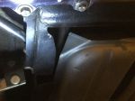
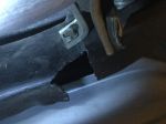
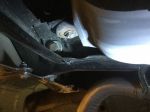
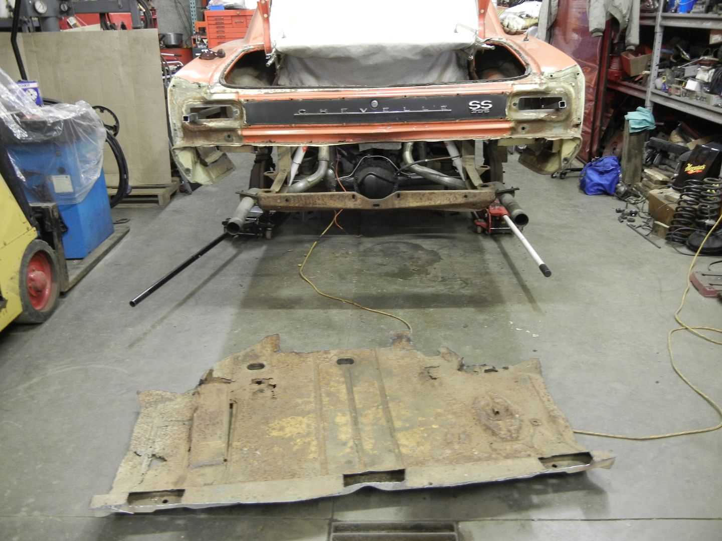
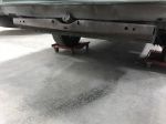
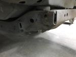
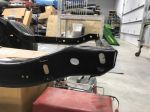
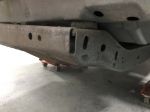
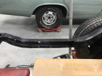
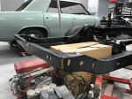
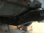
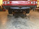
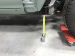
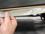
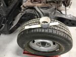
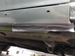
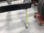
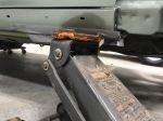
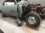
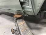
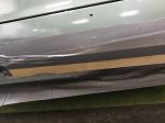
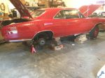
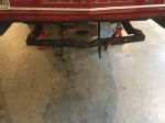
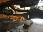
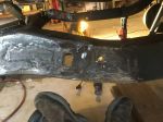
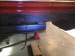
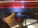
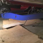
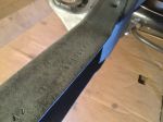
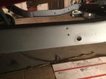
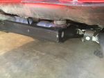
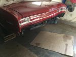
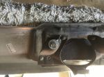
Took demo pictures today.
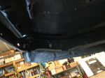
Will post Monday.
Yes, what Mitch said, on the lower rocker edge, NOT on pinch weld.
Wood and tape is to protect paint.
I like the paint stick, because the jack pad wedges up into rocker. Less likely to slip off.
2x2 works well, however, any jiggling may cause it to roll off rocker, not ideal.whew

Either way, take your time.

Karl


__________________

More ambition than brains,

If you have more than 5 of anything, best to stop counting!


2K+ Club

Status: Offline
Posts: 2689
Date:
Permalink  
 

Well the process has started. Removed rear bumper, tail pipes, and gas tank.  Front bumper and other attachments to body tomorrow.  More photos to show what I am dealing with.  No hurry Karl,I am slow in my old age.


Attachments
__________________

Jim L

Lake City


2K+ Club

Status: Offline
Posts: 2689
Date:
Permalink  
 

One last question before I lower the fame or lift the body.  I am going to removed the rocker moldings as Karl suggested.  Removed the screws at the bottom.  Now it appears i must slide the molding up to release it from the clips that are mounted to the rocker and hold the molding on.

I am worried about scratching the paint.  Any suggested, like maybe slide a thin strip of plastic between the molding and the rocker?  Thanks,


__________________

Jim L

Lake City


1K+ Club

Status: Offline
Posts: 1175
Date:
Permalink  
 

Put a layer of tape at upper edge of molding and paint.
Tuck into space between molding.
Spray WD 40 or smear grease on upper edge of molding at tape.
Pull molding slightly out at bottom lift gently moving front to back.
Tape any area above molding where it might scratch if lifted too far.
Safest if done with two people.
Try not to bend the upper flange of molding at retainers.
Karl


__________________

More ambition than brains,

If you have more than 5 of anything, best to stop counting!


1K+ Club

Status: Offline
Posts: 1175
Date:
Permalink  
 

IMG_4106.JPGIMG_4111.JPGIMG_4112.JPGIMG_4113.JPGIMG_4114.JPGIMG_4116.JPGIMG_4117.JPGIMG_4120.JPGIMG_4123.JPG

Measuring and lifting pictures.

Please note elevation difference, loaded, with body, unloaded without body.

I am an advocate of blocking frame at four torque box corners, with wheels off.

Make sure distance to level floor is uniform side to side in those four locations.


Take four additional measurements at rear corners, side to side and rail just before boxed rear kick up area.

Cross check that same area cross member corners to boxed area.

Cross check should be uniform, elevations should match side to side.


If a variance, there may be a problem.

If not document and make re-installed, trimmed piece match those measurements.


Measure, measure, measure.

Document, document, document.


tiphat

Karl


-- Edited by more ambition than brains on Monday 6th of November 2017 01:18:40 PM


-- Edited by more ambition than brains on Monday 6th of November 2017 02:34:18 PM

Attachments
__________________

More ambition than brains,

If you have more than 5 of anything, best to stop counting!


2K+ Club

Status: Offline
Posts: 2689
Date:
Permalink  
 

Looks like the weather is nice today and tomorow, one last chance  to drive the cars.


On another  note i dropped the frame today.  Loosened the two front mount bolts and removed the rest. Duck Tape on the rocker, raised the car up and blocked the body at four positions, placed jack stands at mount position # 2 at 1” below frame. Lowered the car slowly with the floor jacks.

Took measurements, body sitting at 16 5/8 & 17 to bottom of bolt attaching fender support rod At front of car  he re31 & 31 @ rear extension flange.

Now  Frame:

top of frame @ mount #1 is 20 1/16 & 20 1/8

botton of frame @ mount #2 is 11 3/4 & 11 3/4

bottom of frame @ mount # 4 is 14 1/4 & 14 1/2 

top of mount # 6 is 17 3/4 & 17 3/4

top of frame @ mount #7 is  23 1/4 & 22 3/4

Car was hit in drivers side rear sometime in the past, so I expected some variation.  Her are two new photo’s.


-- Edited by jim larson on Tuesday 7th of November 2017 12:15:31 PM


-- Edited by jim larson on Tuesday 7th of November 2017 12:17:02 PM

Attachments
__________________

Jim L

Lake City


1K+ Club

Status: Offline
Posts: 1175
Date:
Permalink  
 

Most of these #s are really close, except for the rear.
Still, little to worry about.
You can probably get the rear elevation almost perfect when fitting cross member.
Which side did you have to shim at the rear mount?

Did you crosscheck rear?
Are we having fun yet?

Karl


__________________

More ambition than brains,

If you have more than 5 of anything, best to stop counting!


2K+ Club

Status: Offline
Posts: 2439
Date:
Permalink  
 

Jim how's the project going? I'm guessing you're out hunting somewhere, but hoping you're not stuck under the car.

__________________

Kevin

Northwestern Ohio


2K+ Club

Status: Offline
Posts: 2689
Date:
Permalink  
 

Just finished the welding and most of the  grinding.  I added a little metal where it was thin due to rust.  I was thinking I should use a little bondo with fiberglass to smooth out the sides where I did the grinding.  Not sure of what to do, so suggestions appreciated.  First bondo/glass, then rust converter then paint.  Take a look at the photos.  What do you guys think?


Attachments
__________________

Jim L

Lake City


President

Status: Offline
Posts: 7274
Date:
Permalink  
 

Get a filler with fiber strands in it. No need to mess with the fiberglass separately. This may be available at a local marine store.  http://www.boatstore.com/evercoat-fibre-glass-100632-everglass-quart.html

ALSO, I would have the body bolted on the frame for the filler smoothing, as it will flex quite a bit from the mount right after the rear wheel to the last crossmember mounts.


-- Edited by Lost in the 60s on Thursday 7th of December 2017 04:13:49 PM

__________________

Mitch D.   River Falls, WI

Lifetime member of the "Cars apart Club"

Some Assembly Required

1966 Chevelle SS 396 M20

1970 Chevelle SS 396 M20

1967 Camaro SS 350 rs


2K+ Club

Status: Offline
Posts: 2689
Date:
Permalink  
 

Thanks for the recommendation Mitch, I see there is both long and short  strand fiberglass.  I plan to use the short fiber type.  Good though about the flex as that could cause a fracture of the dura/glass or Dyno/glass or Bondo/glass or ever/glass.  Quite a range in prices from about $12 to $28 a quart. Wonder is one is better than the other.


-- Edited by jim larson on Thursday 7th of December 2017 09:05:05 PM

__________________

Jim L

Lake City


President

Status: Offline
Posts: 7274
Date:
Permalink  
 

All the reviews I've read about the evercoat products is good. Bodymen rave about their rage products, so I would likely get that.

Maybe Karl has a recommendation ?


__________________

Mitch D.   River Falls, WI

Lifetime member of the "Cars apart Club"

Some Assembly Required

1966 Chevelle SS 396 M20

1970 Chevelle SS 396 M20

1967 Camaro SS 350 rs


1K+ Club

Status: Offline
Posts: 1175
Date:
Permalink  
 

Mitch,

Go down there, pull a bunch more beads with the welder, grind and metal finish.

nanananabeamuprolleyes


Seriously, adding more metal is a better option.

Try and replicate factory thickness even if you have to step back and section in a patch for paper thin perforated area.

All chemical filler products including the duraglass prefer a stable base.  (except those formulated for plastic parts)

Most all of the fiber based products work well and stick well.

Normally when I use them it would normally be a replacement for lead in seams.

Or, pits and deep fills such as badly warped seams that you can't get any straighter.

Base material.

The glass products are also denser and less likely to absorb moisture. 

Remember butchers use "Bondo" craftsman use "chemical filler"

tiphatthumbsup

Mitch's point about flex is valid.

Given our ages, and the use these cars get, consider Mitch's concern, try and make sure metal is as thick as possible and use the glass product you choose.

Highly unlikely it will fall apart in our lifetimes.

2cents

Karl 


__________________

More ambition than brains,

If you have more than 5 of anything, best to stop counting!


2K+ Club

Status: Offline
Posts: 2689
Date:
Permalink  
 

My friend did lay down some metal whe re it was rusted and a little thin, I. Didn’t want to grind that area any more so that’s where I was going to add the glass filler just to smooth it out.  He jokingly said I could add a trailer hitch and haull a couple of 2500 lb bulls.

thanks for the responces  guys.


-- Edited by jim larson on Friday 8th of December 2017 08:29:40 AM

__________________

Jim L

Lake City


2K+ Club

Status: Offline
Posts: 2689
Date:
Permalink  
 

Decided to check frame and body at level, what I did was set floor jacks under differential lower control arm bushings and under the front frame brackets for the front sway bar.  Then set body down on body bushings except for the two most rear mounts.  Everything checked out good And level.  There is a 3/4” & 5/8” gap between the body and the rear crossmember. So I am thinking there will not be much if any flex in the welded area of the frame.  So I plan to add a little everglass or bondo glass and hope for no cracks or smooth out some seam sealer with lacquer thinner.  Here are photos of the rear body mount gaps.


Attachments
__________________

Jim L

Lake City


2K+ Club

Status: Offline
Posts: 2689
Date:
Permalink  
 

Just about Ready for top coat, then put it back together.


Attachments
__________________

Jim L

Lake City


President

Status: Offline
Posts: 7274
Date:
Permalink  
 

What did you decide to do with the fuel line ?

Wish my partial was stamped that clearly. I can barely make mine out.

Is the frame assembly date still on the side, or was that removed with the sectioning ?


__________________

Mitch D.   River Falls, WI

Lifetime member of the "Cars apart Club"

Some Assembly Required

1966 Chevelle SS 396 M20

1970 Chevelle SS 396 M20

1967 Camaro SS 350 rs


2K+ Club

Status: Offline
Posts: 2689
Date:
Permalink  
 

Date is still there, I think some frames are stamped with a part#; but neither my frame or the added section had any.  Trying to find a fuel line where the shipping is a little more reasonable. 

I might go with a OEM steel line as I can get it from amazon for$75 with free prime shipping.


Attachments
__________________

Jim L

Lake City


2K+ Club

Status: Offline
Posts: 2689
Date:
Permalink  
 

All that’s left is to install rear bumper and top off the gas.  Notice bumpers were replaced by Northstar in 94.  Also see the stamp to indicate it’s a origional GM bumper. Can you tell where it was welded?


Attachments
__________________

Jim L

Lake City


1K+ Club

Status: Offline
Posts: 1175
Date:
Permalink  
 

Northstar plating was in Richfield east of Cedar on 66th st.
If I remember right their plant was in Brainerd, now owned by Keystone.
The other popular bumper reconditioner was Gopher Bumper.
They were located off Hiawatha avenue in south Minneapolis.
They did their repairs and plating in Minneapolis.
North Star bought Gopher, Keystone bought North Star to get the rechrome plant in Brainerd.
I think Keystones plant was in Saint Paul, had quality problems, always.
Keystone was and is national, and had/has plants all over country.

We always used North Star or Gopher first, Keystone last, (back in the day)
Keystone was the leader on aftermarket bumpers and parts, they changed the entire industry.

Keystone tried to acquire LKQ corporation, ended up being acquired by them, or the other way around.
Not sure which one ended up owning the other, just remember it was the reverse of where they started.

My last half dozen 66 bars were done by Keystone plant in Brainerd, nice work.
Karl


__________________

More ambition than brains,

If you have more than 5 of anything, best to stop counting!

Page 1 of 1  sorted by
 
Quick Reply

Please log in to post quick replies.

Chatbox
Please log in to join the chat!