Discussion Forum - Northstar Chevelle Club

Members Login
Username 
 
Password 
    Remember Me  
Post Info TOPIC: Air Compressor water filter location???


Active Member

Status: Offline
Posts: 179
Date:
Air Compressor water filter location???
Permalink  


Anybody have a location distance, amount of rise, drop from the compressor? Diagrams, website or just have figured it out. Getting some water in tools and want to figure it out before spraying primer.


Thank you for any help

Brad


__________________


President

Status: Offline
Posts: 7323
Date:
Permalink  
 

I have 50 feet of steel pipe on the ceiling in my shop as a "cooler" before it drops moisture in a drop line. I don't use a dryer and on days when I sand blast, I do get moisture all the way to the pressure pot. The compressor runs almost non-stop for a couple hours. I also have ball valves as drains right after the flex hose from the tank to the wall and at the wall back to hose reel. I open them before every use. I also extended my drain on the bottom of the tank out to daylight and have a ball valve there to drain it every use too.


__________________

Mitch D.   River Falls, WI

Lifetime member of the "Cars apart Club"

1966 Chevelle SS 396 M20

1970 Chevelle SS 396 M20

1967 Camaro SS/RS 350 M20


2K+ Club

Status: Offline
Posts: 2745
Date:
Permalink  
 

bwild70ss396 wrote:

Anybody have a location distance, amount of rise, drop from the compressor? Diagrams, website or just have figured it out. Getting some water in tools and want to figure it out before spraying primer.


Thank you for any help

Brad


 The only things I can think of is to keep it drained via the condensation drain at the bottom of the tank. A series of driers and moisture traps and filters inline also help. The best way I know is probably the most expensive, an air drier unit that removes the condensation. Ive worked at shops with these before and the air is nice and dry at the end of the air lines.


__________________

Chris - Ramsey, MN.

Dear Optimist, Pessimist, and Realist.

While you guys were busy arguing about the glass of water. I drank it!

Sincerly,

The opportunist.


Mega Poster

Status: Offline
Posts: 718
Date:
Permalink  
 

I have a desiccant dryer close to the compressor. In front of it is a water trap. THen I use about 100 feet of hose elevated from the compressor and run it into anoter water trap. Then my paint hose and a small inline desiccant filter. The first dryer is rechargeable and is fairly large. To recharge it you bake the desiccant in the oven.

The other thing is to keep your hose off the floor as much as possible. The floor is cold and the air is warm.

I air condition my space for a day or so to remove the humidity.

Someday I will run the iron pipe like Mitch has. If you run pipe slope the whole run back to the compressor. I've seen people run it horizonaly on the wall back and forth sloped from the compressor.

__________________


Active Member

Status: Offline
Posts: 179
Date:
Permalink  
 

Thank you for the ideas on what to do. When my car body is at the blaster I am going to do a little redoing of my air system.


__________________


2K+ Club

Status: Offline
Posts: 2791
Date:
Permalink  
 

I plumbed my shop about 8 years ago, and had the same trouble finding "recommended" layouts. So I combined what I'd learned and saw at various places.

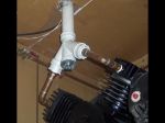
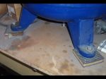
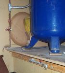
Overall Layout:    (Pic 6) The compressor is on the end of the bench. Under the benchtop at each leg location is a 4x4 post that goes down to the cement floor. Between the compressor legs and the bench is a 1" thick rubber & cork biscuit for vibration isolation.  (Pic 2) To cut down on noise I made up this manifold from copper & PVC pipe, and relocated the intake air filter(s) into the garage attic. I quieted down the unit by 50%.

Main Lines:    I did mine in 1/2" copper. A little spendy, but with the myriad of fittings available it was easier (IMO). I didn't want to fight with threaded pipe, trying to make things work with pre-made lengths, or rent a pipe threading rig. They are pitched at 1/4" per foot, the low point being the main "up-leg" at the compressor.

(Pic 5) Directly off the compressor is a full-flow ball valve (all valves are of this type). This feeds a flexible hose to the main "up-leg". The main goes nearly to the ceiling - calculated backwards from the longest feeder run to allow for the 1/4"per ft. rise. The highest point in the system is end of the feeder pipes. It drops back to the compressor - you want the water to go uphill!

(Pic 8) This details the bottom of the main "up-leg". At the tee off the flexible line there's a vapor & crud drop-leg (like a gas line). I can crack this open and get moisture out easily. At the top of the "up-leg" there is a tee, then shortly after the tee a shut-off valve for each feeder leg around the shop. I can isolate each feeder leg at the source in case of a problem.

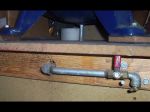
 (Pic 7) When it was decided to go on the bench, I had to figure out a way to drain the tank! I removed the petcock and extended the drain through the benchtop, and elbow'd over & out the front. Easy to drain!

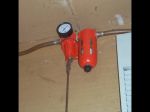
(Pic 3) On each feeder leg there is a water trap and regulator, before any feed drops. They are attached to the feed line using unions (out of the picture). This way if the device goes bad, I can break the feed line, lower the whole device down and fix it. I made up a "short-guy remote control" for the regulator (some 3/16" steel rod) so I can adjust pressure from the floor). At the end of each feeder leg there is a drop pipe to the floor with a drain valve.

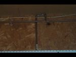
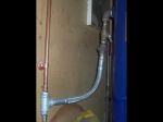
(Pic 1) Drop Lines. Off each main feeder leg (post regulator/water trap) there are several drops along the bench. Each drop is tapped in with one of these "up & over" assemblies to keep water out (the stand-off's used to mount the main feeders really helped with this!) At the bottom of the feeder drops I used a cast bronze shower head elbow fitting. This fitting has mounting screw ears cast in, so it's easy to get a secure mount to the wall. On each of these fittings is a Milton quick connect for air lines.

Other Tips:

I have a tool auto-oiler rig, fitted with a male on the inlet, female on the outlet. I can click it into any drop-leg port for oiled air. (see next tip!!)

I have 2) 25' air hoses. One is specifically dedicated for air tools and oiler use, the other for anything else (like paint guns!). They are marked with tags and I painted the couplers to not screw them up.

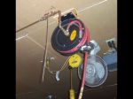
(Pic 4) The hose reel detail. This is on dry air, and no way to put the oiler in-line. I've got a "short-guy" adapter on the shut-off valve so I can turn off the air without a stepstool.

Hope this gives you a few ideas!!headscratch


Attachments
__________________


John D. - St. Louis Park, MN.

1965 El Camino - LT-1, 4L60e, 4wh discs, SC&C susp.
2013 F-150 Platinum - Twin Turbo 3.5

2018 Factory Five MkIV Roadster build thread


Active Member

Status: Offline
Posts: 179
Date:
Permalink  
 

if you are going to use drip legs you should run 50 feet of line before you try to catch water in drip leg. takes about 50 feet for that vapor to be all liquid.

__________________

frank s---st paul

64' chevelle--37' chevy coupe


Active Member

Status: Offline
Posts: 179
Date:
Permalink  
 

line coming from right is the 50 footer. drip legs down to floor. this is out of car craft mag many moons ago.


Attachments
__________________

frank s---st paul

64' chevelle--37' chevy coupe


Active Member

Status: Offline
Posts: 179
Date:
Permalink  
 

Some more good info. Thank you guys.


__________________
Page 1 of 1  sorted by
 
Quick Reply

Please log in to post quick replies.

Chatbox
Please log in to join the chat!